 |
| ||||||||
 |
 |
 |
 |
 |
|
Frame Relay is a protocol standard for LAN internetworking which provides a fast and efficient method of transmitting information from a user device to LAN bridges and routers. The Frame Relay protocol uses a frame structured similar to that of LAPD, except that the frame header is replaced by a 2-byte Frame Relay header field. The Frame Relay header contains the user-specified DLCI field, which is the destination address of the frame. It also contains congestion and status signals which the network sends to the user. Virtual Circuits The Frame Relay frame is transmitted to its destination by way of virtual circuits (logical paths from an originating point in the network) to a destination point. Virtual circuits may be permanent (PVCs) or switched (SVCs). PVCs are set up administratively by the network manager for a dedicated point-to-point connection; SVCs are set up on a call-by-call basis. Advantages of Frame Relay Frame Relay offers an attractive alternative to both dedicated lines and X.25 networks for connecting LANs to bridges and routers. The success of the Frame Relay protocol is based on the following two underlying factors:
These two factors make Frame Relay a desirable choice for data transmission; however, they also necessitate testing to determine that the system works properly and that data is not lost.
Standards for the Frame Relay protocol have been developed by ANSI and CCITT simultaneously. The separate LMI specification has basically been incorporated into the ANSI specification. The following discussion of the protocol structure includes the major points from these specifications. The Frame Relay frame structure is based on the LAPD protocol. In the Frame Relay structure, the frame header is altered slightly to contain the Data Link Connection Identifier (DLCI) and congestion bits, in place of the normal address and control fields. This new Frame Relay header is 2 bytes in length and has the following format:
Frame Relay header structure DLCI C/R EA FECN BECN DE Information Explicit Congestion Notification (ECN) Bits When the network becomes congested to the point that it cannot process new data transmissions, it begins to discard frames. These discarded frames are retransmitted, thus causing more congestion. In an effort to prevent this situation, several mechanisms have been developed to notify user devices at the onset of congestion, so that the offered load may be reduced. Two bits in the Frame Relay header are used to signal the user device that congestion is occurring on the line: They are the Forward Explicit Congestion Notification (FECN) bit and the Backward Explicit Congestion Notification (BECN) bit. The FECN is changed to 1 as a frame is sent downstream toward the destination location when congestion occurs during data transmission. In this way, all downstream nodes and the attached user device learn about congestion on the line. The BECN is changed to 1 in a frame traveling back toward the source of data transmission on a path where congestion is occurring. Thus the source node is notified to slow down transmission until congestion subsides.
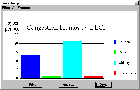
Bytes with congestion bits set according to DLCI value Consolidated Link Layer Management (CLLM) It may occur that there are no frames traveling back to the source node which is causing the congestion. In this case, the network will want to send its own message to the problematic source node. The standard, however, does not allow the network to send its own frames with the DLCI of the desired virtual circuit. To address this problem, ANSI defined the Consolidated Link Layer Management (CLLM). With CLLM, a separate DLCI (number 1023) is reserved for sending link layer control messages from the network to the user device. The ANSI standard (T1.618) defines the format of the CLLM message. It contains a code for the cause of the congestion and a listing of all DLCIs that should act to reduce their data transmission to lower congestion. Status of Connections (LMI) Each DLCI corresponds to a PVC (Permanent Virtual Circuit). It is sometimes necessary to transmit information about this connection (e.g., whether the interface is still active) the valid DLCIs for the interface and the status of each PVC. This information is transmitted using the reserved DLCI 1023 or DLCI 0, depending on the standard used. A multicast status may also be sent with the LMI. Multicasting is where a router sends a frame on a reserved DLCI known as a multicast group. The network then replicates the frame and delivers it to a predefined list of DLCIs, thus broadcasting a single frame to a collection of destinations. Discard Eligibility (DE) When there is congestion on the line, the network must decide which frames to discard in order to free the line. Discard Eligibility provides the network with a signal to determine which frames to discard. The network will discard frames with a DE value of 1 before discarding other frames. The DE bit may be set by the user on some of its lower-priority frames. Alternatively, the network may set the DE bit to indicate to other nodes that a frame should be preferentially selected for discard, if necessary.
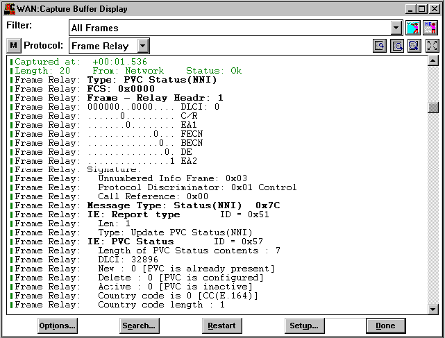
ANSI T1.618 T1.618 describes the protocol supporting the data transfer phase of the Frame Relay bearer service, as defined in ANSI T1.606. T1.618 is based on a subset of ANSI T1.602 (LAPD) called the "Core Aspects" and is used by both switched and permanent virtual calls. T1.618 also includes the Consolidated Link Layer Mechanism (CLLM). The generation and transport of CLLM is optional. With CLLM, DLCI 1023 is reserved for sending link layer control messages. T1.618 issues implicit congestion notification from the network to the user device. The congestion notification contains a code indicating the cause of the congestion and lists all DLCIs that have to reduce their traffic in order to lower congestion. ANSI T1.617 To establish a Switched Virtual Circuit (SVC) connection, Frame Relay users must establish a dialog with the network using the signalling specification in T1.617. The procedure results in the assignment of a DLCI. Once the dialog is established, the T1.618 procedures apply. To establish a Permanent Virtual Circuit (PVC), a setup protocol is used which is identical to the ISDN D-channel protocol and defined in T1.617. With ISDN, users can use the D-channel for setup. For non-ISDN callers, there is no D-channel, so the dialog between the user and the network must be separated from the ordinary data transfer procedures. In T1.617, DLCI 0 is reserved. T1.617 also contains specifications on how Frame Relay service parameters are negotiated. ANSI LMI ANSI LMI is a Permanent Virtual Circuit (PVC) management system defined in Annex D of T1.617. ANSI LMI is virtually identical to the Manufacturers’ LMI, without the optional extensions. ANSI LMI uses DLCI 0. Manufacturers’ LMI Manufacturers’ LMI is a Frame Relay specification with extension-document number 001-208966, September 18, 1990. Manufacturers’ LMI defines a generic Frame Relay service based on PVCs for interconnecting DTE devices with Frame Relay network equipment. In addition to the ANSI standard, Manufacturers’ LMI includes extensions and LMI functions and procedures. Manufacturers’ LMI uses DLCI 1023. Frame Relay NNI PVC (FRF.2) Your analyzer also supports the decoding of Network-to-Network (NNI) PVC frames according to the Frame Relay Forum implementation agreement FRF.2. The NNI interface is concerned with the transfer of C-plane and U-plane information between two network nodes belonging to two different Frame Relay networks. Such frames are automatically recognized by the analyzer and correctly displayed. NNI PVC decode
FRF.3 FRF.3 provides multiprotocol encapsulation over Frame Relay within an ANSI T1.618 frame. The structure of such a Frame Relay frame is as follows:
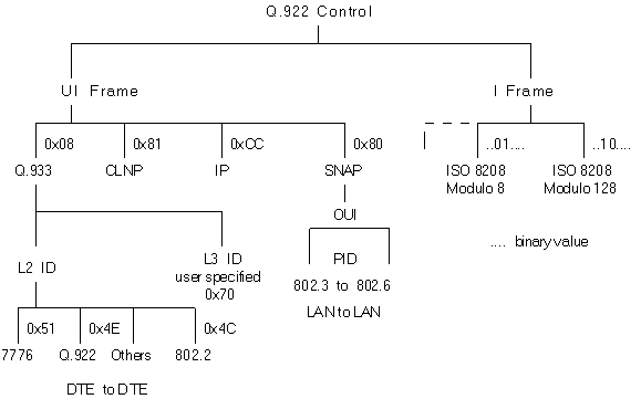
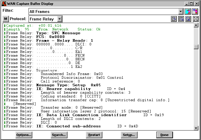
FRF.3 frame structure The NLPID (Network Level Protocol ID) field designates what encapsulation or what protocol follows. The following diagram details the possible values for NLPID and the protocols which are designated by each value: Multiprotocol encapsulation over Frame Relay For example, a value of 0xCC indicates an encapsulated IP frame. UNI SVC (FRF.4) FRF.4 is Frame Relay switched virtual connection user-to-network interface agreement. It applies using equipment attached to a non-ISDN Frame Relay network or to an ISDN network using only case A. UNI SVC decode Following is a list of valid SVC message types:
FRF.5 FRF.5 defines Network internetworking connecting Frame Relay over ATM. Refer to (Frame Relay over ATM) for more details. FRF.8 FRF.8 defines Service
internetworking connecting Frame Relay over ATM. Refer to (Frame
Relay over ATM) for more details. FRF. 9 This is the encapsulation of the Data Compression Protocol (DCP) over Frame Relay. It applies to unnumbered information (UI) frames encapsulated using Q.933 Annex E [9] and FRF.3.1 [3] It may be used on Frame Relay connections that are interworked with ATM using FRF.5. DCP is logically decomposed into two sublayers: the DCP Control sublayer, and the DCP Function sublayer. The Data Compression Protocol (DCP) is encapsulated with Multiprotocol Encapsulation over a Frame Relay network using Q.933 Annex E. A DCP PDU is the combination of a DCP Header and DCP Payload or DCPCP PDU. DCP PROTOCOL DATA UNIT FORMAT The DCP PDU is used by a DCP entity to communicate data or control information to the remote peer DCP entity. The most significant (earliest sent) octet(s) of the DCP PDU must be the DCP Header. The C/D bit of the DCP Header signals whether the DCP PDU is for control or for data. DCP Data PDU Format A DCP data PDU encapsulates compressed or uncompressed user data for transport to the peer DCP entity. The DCP Header is one or three octets in length and is described by the first two lines of the diagram below.
E C/U R-A R-R C/D DCCI Reserved The DCP Control Protocol (DCPCP) is used to enable, disable, and optionally configure DCP. DCPCP has two modes of operation: Mode-1 and Mode-2. Mode-2 provides full negotiation capabilities to enable, disable, and configure DCP using the Point-to-Point Protocol (PPP) Link Control Protocol (LCP) negotiation procedures. Mode-1 uses a subset of the Mode-2 negotiation primitives with simplified procedures to enable and disable DCP with the default DCFD and default parameter values. Mode-1 operation is required; Mode-2 operation is optional. The length of a DCP Header for DCP control PDUs is one octet. DCPCP PDUs use the same formats as the PPP LCP as defined in RFC 1661, DCPCP Mode-1 uses a subset of the DCPCP PDU formats (Configure-Request and Configure-Ack with the Mode-1 Configuration Option only). The format of the DCPCP packet consists of the header followed by the PDU which uses the same format as the PPP LCP as shown below.
DCPCP PDU structure Code Identifier Length Data
DCPCP configuration options Type Length Revision Mode 1 Request and response messages The Mode-1 Request message is a DCPCP Configure-Request packet with the Code field set to 1, the Mode-1 Response message is a DCPCP Configure-Ack packet with the Code field set to 2. Mode-2 Formats Mode-2 formats are the same as the LCP packet formats as shown above, with a unique set of Configurations options. The LCP packets with codes 1 through 7 are required. The other LCP packets specified in RFC 1661 and listed above are optional. NNI SVC (FRF.10) Your analyzer also supports the decoding of Network-to-Network (NNI) SVC frames according to the Frame Relay Forum implementation agreement FRF.10. This implementation agreement applies to SVCs over Frame Relay NNIs and to SPVCs. It is applicable at NNIs whether both networks are private, both are public or one is private and the other public. Such frames are automatically recognized by the analyzer and correctly displayed. FRF.12 is the Frame Relay Fragmentation Implementation Agreement. Fragmentation queuing reduces both delay and delay variation in Frame Relay networks by dividing large data packets into smaller packets and then reassembling the data into the original frames at the destination. This ability is particularly relevant to users who wish to combine voice and other time-sensitive applications, such as SNA mission-critical applications, with non-time-sensitive applications or other data on a single Permanent Virtual Circuit (PVC). The main benefit of fragmentation is the ability to utilize common User to Network Interface (UNI) access lines or Network to Network Interface (NNI) lines and/or PVCs for communications combining large data frames and real-time protocols. Fragmenting frames enhances the utility and uniformity of Frame Relay networks, reducing delay and delay variation while upgrading application responsiveness, quality and reliability. As a result, multiple types of traffic, such as voice, fax and data, can be transparently combined on a single UNI, NNI and/or PVC. The Fragmentation Implementation Agreement provides for transmission of Frame Relay Data Terminal Equipment (DTE) and Data Communications Equipment (DCE) with the ability to fragment long data frames into a sequence of shorter frames that are then reassembled into the original frame by the receiving peer DTE or DCE. Frame fragmentation is necessary to control delay and delay variation when real-time traffic, such as voice, is carried across the same interfaces as data traffic. Fragmentation enables the interleaving of delay-sensitive traffic on one PVC with fragments of long data frames on another PVC using the same interface. FRF.12 supports three fragmentation applications:
When used end-to-end, the fragmentation procedure is transparent to Frame Relay network(s) between the transmitting and receiving DTEs.
FREther FREther is a variant of Frame Relay which is comprised of the Frame Relay header followed by the EtherType field. This is an additional form of encapsulation over Frame Relay which is used by some customers. BRE (Bridge Relay Encapsulation) is a proprietary Ascom Timeplex protocol that extends bridging across WAN links by means of encapsulation. BRE2 is an improved form of the standard, providing better performance due to the fact that it sits directly on the link layer protocol, requires less configuration and provides its own routing protocol. BRE2 was deployed in 4.0 router software and is available in all 4.x and 5.x versions of the software. The format of the BRE2 frame is as follows:
BRE2 frame format If F is 0 than the frame is unfragmented and the BRE2 header is 17 bytes long. If F is 1, the frame is fragmented and the BRE2 header is 22 bytes long. SRB # is the Source Route Bridge Number (4 bits).
In order to provide a Frame Relay service, Regional Bell Operating Companies (RBOCs) deploy Cascade switches in multiple LATAs and interconnect them to provide service to customers across the LATAs, as well as manage the switches in multiple LATAs from a single network management station. The trunk header format for the Cascade STDX family of switches conform to ANSI T1.618-1991 ISDN Core Aspects of Frame Protocol for use with Frame Relay Bearer Service. The Cascade trunk header format is as shown below:
Cascade trunk header format R C/R Version ODE DE BECN FECN VC priority For management data, a 5th byte contains information concerning the type of PDU information to follow. Values are as follows:
The purpose of LAPF is to convey data link service data units between DL-service users in the U-plane for frame mode bearer services across the ISDN user-network interface on B-, D- or H-channels. Frame mode bearer connections are established using either procedures specified in Recommendation Q.933 [3] or (for permanent virtual circuits) by subscription. LAPF uses a physical layer service, and allows for statistical multiplexing of one or more frame mode bearer connections over a single ISDN B-, D- or H-channel by use of LAPF and compatible HDLC procedures. The format of the header is shown in the following illustration:
LAPF address format
LAPF format EA C/R FECN BECN DLCI DE D/C N(S) N(R) P/F X Su M
| |||||||||||||||||||||||||||||||||||||||||||||||||||||||||||||||||||||||||||||||||||||||||||||||||||||||||||||||||||||||||||||||||||||||||||||||||||||||||||||||||||||||||||||||||||||||||||||||||||||||||||||||||||||||||||||||||||||||||||||||||||||||||||||||||||||||||||||||||||||||||||||||||


